Creating a break line
|
Mode |
Tool |
Tool set |
|
Modes for Creating single lines |
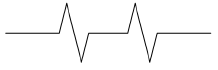
Break Line
|
Dims/Notes |

The Break Line tool creates one of three types of break lines: straight, curved, or arc.
On site models, pads with open edges, sometimes called break lines, can be created using the Site Modifier tool (Vectorworks Architect or Landmark required). See Creating a planar pad from grade limits.
To draw a break line:
Click the tool and mode.
Click to place the object in the drawing, and click again to set the rotation. The first time you use the tool in a file, a properties dialog box opens. Set the default parameters. The parameters can be edited from the Object Info palette.
Click to show/hide the parameters.Click to show/hide the parameters.
|
Parameter |
Description |
|
Break Style |
Selects the style of the break line (Straight, Curved, or Arc) |
|
Break Width |
Indicates the width of the break only |
|
Break Height |
Indicates the height of the break only |
|
Break Radius |
Sets the radius of the break only |
|
Number of Breaks |
Indicates whether a single or multiple break should be drawn |